Preprocessing, transformations
Transformation setup (Setup button) |
 |
Transform block applies a transformation to the input vectors of the events from DataSet's connected to the input (left >> button) and sends resulting data to the DataSet's connected do the output (right >> button). Event vectors in the input DataSets's remain unchanged. Events in the output DataSets's are constructed according to the output format mapping and filter rules.
To add the Transform block to the project choose menu Edit - Add Component - Transform.
Transformation setup (Setup button)
Setup options are arranged in tabs: general info, transformation setup, output format and filter setup and triggering setup.
Apply button saves all parameters but doesn't start calculations; Go! button saves parameters and starts calculations, it is enabled only in manual trigger mode.
general info
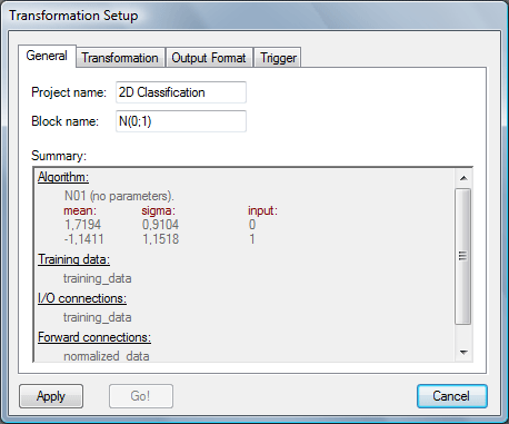
Block and project names may be chnged here (names should not contain "\" symbols).
Summary shows the current transformation setup.
transformation setup
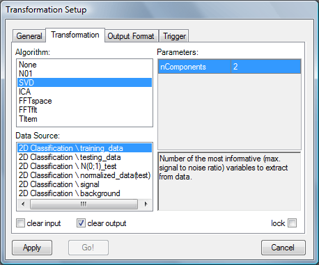
Linear Transformations
Note: DataSet connected to the input of the Transform block may be used simultaneously as a data source (reference set used to calculate transformation parameters).
None: Doesn't perform any transformation. Useful when mixing of the vector elements is required. Also may be used as a buffer for delaying data in loops.
N(0,1): Normalization to zero-mean and unitary standard deviation. Uses reference DataSet selected in the Data Source list to calculate mean values μi and standard deviations σi for each position i in the event input vector. Obtained values are used to normalize input vectors of the processed events: outputi = (inputi - μi) / σi. The outputi values are available in Output Format tab as
o1, o2, etc.SVD: Quotient Singular Value Decomposition. Uses reference DataSet selected in the Data Source list to calculate mixing matrix that transforms event's input vector from the original space to the QSVD space. This is an orthogonal transformation. Axes of the QSVD space show directions where ε = σsignal / σbackground have the largest values. In this implementation axes are ordered in the descending order of max(ε, ε-1). Parameter nComponents selects how many most informative dimensions you need in the resulting space (note: there will be equal number of outputs /
o1, o2, .../ accessible in Output Format tab). Transformation needs to know if the reference event is a signal or a background - this is recognized by the target value (target vector must contain only one elementt1in this case): following values are considered as a signal:1.0, 0.95and0.9, and as a background:0.1, 0.05, 0.0, -0.9, -0.95, -1.0.ICA: Independent Component Analysis. Uses reference DataSet selected in the Data Source list to calculate mixing matrix that transforms event's input vector from the original space to the ICA space. This is a non-orthogonal transformation. Axes of the ICA space show the directions where a measure of non-gausianity have the largest values. Data distributions in the directions of ICA axes are forced to be uncorrelated one to each other. If this condition cannot be met - transformation will be stopped and message window will inform you about the reason. No information about signal/background is required and there are no restrictions on the target vector length. Axes are ordered in the descending order of kurtosis value k = EX4 - 3(EX2)2 and you can select the number of the most "independent" dimensions (nComponents parameter).
TItem: Transformation based on the reference Transform block selected in the Data Source list. Does exactly the same calculations as the referenced block.
lock: Locks the transformation's parameters. Parameters are calculated only once (if they were ready before locking, the existing parameters will be preserved). When the project is saved to the file with lock option checked - parameters are written to the project file and will be used next time the file is opened. This is particularly useful for ICA decomposition, which may give different results on each run.
Fourier Transformation
FFTspace: Transformation of the event's input vector to the frequency domain. Resulting vector consists of an amplitude spectrum followed by a phase spectrum.
FFTflt: FFT filter, event's input vector is filtered in the frequency domain and then inverse FFT is performed. Frequencies below the LoBound and above the HiBound threshold are removed.
clear input: Input DataSets will be cleared after processing.
clear output: Output DataSets will be cleared before processing. If unchecked - new events will be attached to the existing ones.
output format and event filter setup
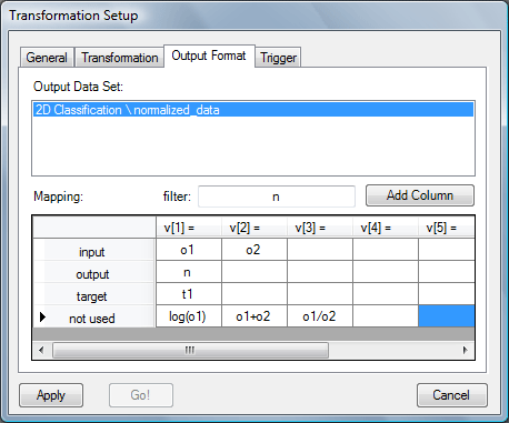
When transformation is applied to the event, its input vector is processed. Resulting output vector (acessed witho1, o2, ...) is used to compose vectors of the destination events. Output vector itself is not stored in the source event's. Destination events in each output DataSet may be composed in a different way. Select a DataSet in the Output Data Set list and put desired expressions for destination event vectors in the Mapping table. Vector lengths are adjusted to the number of non-empty table cells. If more table columns is required, click Add Column button.
Simple example in the image above performs the following mapping:
Events stored in the output DataSets can be filtered (in the example from the image above filter is turned off).destination event input vector will be composed of the first and second element of the temporary source event output vector; destination event output vector will be created with the length = 1 and it will be initialized to 0.0(not-used entrynwithout the index);destination event target vector will be created from the first element of the source event target vector; destination event not-used vector will not be composed of three elements, calculated as a different combinations of the transformation output.
triggering setup
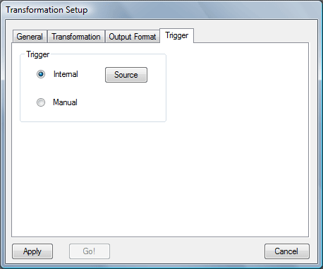
If Manual mode is selected, Go! button is enabled and it releases calculations. If Internal mode is chosen - Source button is enabled and it allows to select source of the trigger through the common Connection Add dialog window (Go! button is disabled); processing starts when one of the selected sources finished its own task.
Input list (left >> button)
Left button >> holds the list of the source DataSet's; it opens Connection Add dialog window. Double-click on the item from the Available list adds new connection. Double-click on the item from the Added list removes the connection.
Output list (right >> button)
Connects the output of the Transform block to the destination DataSets. Opens common Connection Add dialog window.